Autor plague70

porplague70

Xeams: Sistema de anti-spam OpenSource.

Xeams For Linux


Installation Instructions

Follow the steps below to install Xeams on a Linux machine.

  • Log in as root
  • Download the installer
  • Extract the tar file using the following command
    tar -xf XeamsLinux.tar
  • Ensure the permissions for Install.sh is set as an executable. If not, use the chmod +x Install.sh command to change its permission
  • Execute Install.sh script
  • By default, the installation script will install the server in /opt folder. You can change this location to any other value if desired. Additionally, it will create necessary scripts in /etc/init.d/ folder so that the server comes up when you restart the machine.
  • Using your browser connect to http://localhost:5272
porplague70

Failover no PFSense 2.0.0

Failover no PFSense 2.0.0

Segue a seguir o procedimento e failover aplicado no PFSense 2.0.0. O cenário utilizado é com 2 conexões com a internet (WAN) e apenas 1 conexão de rede local (LAN).

Observação.: O servidor possui 3 placas de rede, 2 conectadas a internet e 1 conectada a rede interna. Na instalação eu defini apenas 1 wan e 1 lan. A segunda placa wan será configurada abaixo.

Vamos iniciar ativando a segunda interface WAN. Vá em: Interfaces > Assign

Clique no Botão Add:

Imediatamente o PFSense vai adicionar a interface restante. Agora basta clicar em Save

Agora vamos ativar e renomear a interface para evitar confusão. Vá em Interfaces > OPT1

Clique em Enable Interface, Altere o campo Description para WAN2, defina o tipo de conexão em Type para DHCP e clique em salvar.

Agora precisamos definir os endereços de servidores DNS, para isso vamos no menu System, opção General Setup:

Preencha os campos com o seus servidores DNS de cada provedor de acesso e defina a respectiva interface de conexão, ou faça como eu e defina os servidores DNS do google para cada interface:

8.8.8.8 – WAN
8.8.4.4 – WAN
8.8.8.8 – WAN2
8.8.4.4 – WAN2

Agora vamos iniciar o processo de configuração do failover propriamente. Vamos definir um Grupo de gateways, para isso vá em System > Routing:

confirme na aba Gateways que os gateways das interfaces WAN e WAN2 estão preenchidos.

Agora entre na aba Groups e clique no botão Add:

Preencha os campos da seguinte forma:

Group Name: Multilan
Gateway priority:
* Tier1 – WAN
* Tier 2 – WAN2
trigger Level: Packet Loss

Depois disso basta clicar em Save.

Depois desses passos vamos as configurações de Firewall. Vá em Firewall > Rules:

Entre na aba Floating e clique no botão Add new rule:

Preencha os campos da seguinte maneira:

Action: Pass
Interface: Selecione WAN e WAN2
Direction: Out
Protocol: TCP
Source: Any
Destination: Any
Destination Port Range
* From: HTTP
* To: HTTP

Desça a barra de rolagem até Advanced Features, Clique no botãoAdvanced na opção Gateway e selecione Multilan:

Salve e vá para Firewall > NAT:

Vá para a guia Outbound e marque a opção Manual Outbound NAT rule generation e salve. As regras abaixo irão aparecer na sua tela:

Vamos adicionar duas regras. Clique no botão Add e preencha os seguintes campos:

Interface: WAN
Protocol: Any
Source: Any
Destination: Any
Translation: Interface address

e clique em salvar.

Repita o procedimento criando nova regra só alterando a interface WAN por WAN2:

O resultado será a tela abaixo:

Pronto, o failover já estará funcionando. Agora só nos resta testar e confirmar que ele está realmente OK.

porplague70

Instalando pfSense utilizando um pendrive.

Instalando pfSense utilizando um pendrive

Criei um blog novo, que vou levar adiante. Além de pFsense, o blog trará conteúdos do mundo da tecnologia.

Atualizei este tutorial no novo blog, então, peço que todos verifiquem a versão atualizada deste tutorial no novo site:

http://www.techtest.com.br/2015/02/instalando-pfsense-utilizando-um.html

Aproveitem para conhecer o site!

Grato a todos!

——————————————————-

Olá galera!

Hoje vou compartilhar uma dica muito valiosa.

Como instalar o pfsense utilizando um pendrive como mídia, ao invés de um CD-ROM.

Muito útil para aqueles micros que não tem drive de cd, além de ser mais prático e rápido.

É muito simples.

Vai precisar apenas de um pendrive e dos seguintes programas:

Alexander Beug’s USB Image ToolDownload
pfSense memdisk image – Download

Extraia a imagem do pfsense para algum lugar em seu computador.
Extraia o USB image tool para uma pasta qualquer e depois execute.

ATENÇÃO! Esse procedimento vai apagar todos seus arquivos no seu pendrive!

Selecione o pendrive desejado na lista e clique no botão restore. Será exibida uma tela para escolher uma imagem. Escolha a que extraiu do pfSense.

Pronto! O programa vai começar a gravar a imagem no pendrive. Depois, é só dar boot na máquina que deseja instalar o pfSense com o pendrive e a instalação vai funcionar normalmente, como se fosse pelo CD.

Testei em um Sandisk de 4gb e funcionou perfeitamente.

Tutorial baseado na dica do Spook, no forum do pfSense.

porplague70

UPGRADE / ATUALIZAÇÃO DO ENDIAN FIREWALL

Antes de mais nada é bom fazer um backup.

acesse a console do seu Endian:

https://ipdoendian:10443

Usuário: admin

No menu do lado esquerdo entre em cópia de segurança, gere um novo backup e salve em sua máquina fazendo download dele.

Ainda no menu do lado esquerdo habilite a opção de SSH.

Para conseguir fazer atualizações antes é preciso se cadastrar no site do Endian:

Feito o cadastro, acesse o seu Endian por SSH, usuário root.

Próximo passo é dar o comando para ele verificar e atualizar o servidor.

# efw-upgrade

1) Production (stable releases)
2) Development (bleeding edge)
1
Please enter your username and hit [ENTER]:

Nesse campo coloque o email que foi cadastrado no site da Endian, enter.

Ele vai começar a baixar os pacotes de atualização do seu Endian Community.

porplague70

Pfsense+Squid+SquidGuard logando no Active Directory

Pfsense+Squid+SquidGuard logando no Active Directory


Na aba “Available Packages” procure por “squid” e mande instalar clicando no ícone no canto direito

Imediatamente você será direcionado para a página do Package Installer, nele veremos o progresso da instalação do pacote squid e suas dependências:

Vamos inserir as regras para a rede LAN:

OBS.: LAN net = LAN subnet

Agora vamos no menu Services > Proxy Server:

Na aba “General” certifique que “Transparent Proxy” está desmarcada.

Considerando que seu servidor wk3 está com o IP: 192.168.1.12, a senha do usuário Administrador é “pwd1admin” e seu domínio é prototipo


Na aba “Auth Settings” vamos adicionar os seguintes parâmetros:


Authentication method: LDAP

LDAP version: 3

Authentication server: 192.168.1.12

Authentication server port: 389

LDAP server user DN: cn=Administrador,cn=Users,dc=prototipo

LDAP password: pwd1admin

LDAP base domain: dc=prototipo

LDAP username DN attribute: uid

LDAP search filter: sAMAccountName=%s

OBS: Meu domínio coloquei somente o nome prototipo, não coloquei nada como .com.br ou .com


Após este processo o squid estará buscando os usuários pelo Ad, agora precisamos instalar o SquidGuard para que ele possa controlar estes usuários na rede.

Vá na aba Blacklist e baixe no site da shallalist os arquivos, ou cole na blacklist upload:http://www.shallalist.de/Downloads/shallalist.tar.gz

Vá na aba Common ACL e acesse Target Rules List e de um Deny no Default access All

Agora vamos adicionar em Group ACL os grupos que já temos cadastrados no Active directory.

No meu exemplo tenho cadastrado somente dois, um deles é “Internet-TI” “Internet-Padrao”, deixe-os  com letras maiúsculas ou minúsculas do jeito que postou no Active Directory.

Note que no campo cliente, possui alguns usuários, é importante adiciona-los pois o SquidGuard vai bloquear de acordo com as especificações que você adicionará logo em Target Rules list


No meu exemplo, o Grupo Internet-TI terá bloqueado somente webmail.

Para fazer o teste, clique em save e volte para a aba General Settings e deixe de acordo com a tela abaixo.


Assim que o squidguard iniciar ficará com status start. Aí é só testar.

Para fazer o teste fui no Internet Explorer e vá em Ferramentas>Opções da Internet>Configurações da LAN


Configure de acordo com o Ip de seu PfSense.

Agora de um Ok e Ok

Feche o navegador e abra-o novamente e agora coloque o login e senha do grupo que adicionou, no meu caso Internet-TI


Agira vou acessar um site que contenha webmail. Ex: www.hotmail.com.br


Este é o resultado.

porplague70

Squid + Autenticação NCSA + Controle de Acesso por Grupos

Squid + Autenticação NCSA + Controle de Acesso por Grupos

Esse tutorial busca ajudar aqueles que necessitam montar um servidor proxy aonde os usuários precisem ser autenticados, separados por grupos e que cada grupo tenha uma lista específica de sites liberados para acesso, de uma forma prática e rápida sem ter que usar algum tipo de integração como o AD, Samba ou LDAP.

Parte 1 – Instalação do Squid

Vá no menu ”System > Packages”, na tela que se segue clique em ”Available Packages” e procure na lista o Squid. Clique na setinha ao lado da linha do Squid para instalar o pacote. Com a instalação bem sucedida do Squid vamos à próxima etapa.

Figura 1: Menu System > Packages

Figura 1: Menu System > Packages

Figura 2: Pacote do Squid

Figura 2: Pacote do Squid

Figura 3: Instalação bem sucedida do Squid.

Figura 3: Instalação bem sucedida do Squid.

Parte 2 – Configurações Básicas do Squid

Vamos realizar a configuração básica do nosso Proxy. Para isso vamos acessar as configurações do Squid no menu ”Services > Proxy Server”.

Figura 4: Configurações Básicas do Squid.

Figura 4: Configurações Básicas do Squid.

Na aba “General”, estão localizadas as configurações básicas do nosso servidor proxy. Geralmente não é preciso alterar nada para que o proxy funcione. Então vamos deixar os valores como padrão para a maioria dos campos, alterando somente o campo”Language” para “Portuguese” (isso fará com que o Squid exiba as páginas de erro em Português) e um pouco mais abaixo vamos marcar a opção ”Supress Squid Version”(para que o Squid não mostre a sua versão na página de erros). E por fim clicamos em”Save” para guardar nossas configurações.

Figura 5: Continuação das Configurações Básicas do Squid

Figura 5: Continuação das Configurações Básicas do Squid

Figura 6: Continuação das Configurações Básicas do Squid

Figura 6: Continuação das Configurações Básicas do Squid


Parte 3 – Configurações de Autenticação do Squid

Ainda nas configurações do Squid, vamos até a aba “Auth Settings”. Aqui vamos configurar nosso Squid para que ele utilize a base de dados Local. Então vamos até o campo ”Authentication Method” e vamos escolher a opção “Local”.

Figura 7: Configurações de Autenticação do Squid

Figura 7: Configurações de Autenticação do Squid

Ainda nessa tela temos 3 campos importantes:

“Authentication prompt”: Texto que vai ser exibido na janela que pede o usuário e a senha.
“Authentication processes”: Número de autenticações simultâneas. Ajuste conforme preciso.
“Authentication TTL”: Este campo define o tempo de vida da sessão de um usuário autenticado.

Figura 8: Configurações de Autenticação do Squid

Figura 8: Configurações de Autenticação do Squid

Clicamos em ”Save” e vamos à próxima etapa.

Parte 4 – Cadastro de novos usuários

Nas configurações do proxy na aba “Local Users”, vamos cadastrar os 3 usuários para utilizarmos no nosso exemplo. Para cadastrar um usuário clique no ícone da setinha marcado na figura abaixo.

Figura 9: Cadastros de Usuários no  Squid

Figura 9: Cadastros de Usuários no Squid

Na tela que se abre, temos 2 campos obrigatórios: ”Username” e ”Password”. Já o campo “Description” é opcional, porém é muito útil para caráter administrativo. No nosso exemplo eu usei esse campo para definir qual departamento o usuário pertence. Clicamos em “Save” para finalizar essa etapa de cadastro.

Figura 10: Continuação dos Cadastros de Usuários no  Squid

Figura 10: Continuação dos Cadastros de Usuários no Squid

Parte 5 – Administrando Usuários: Remover Usuário e Troca de Senha

Ainda em “Local Users”, podemos perceber que na listagem dos usuários cadastrados no sistema, ao lado aparece dois pequenos ícones, eles são a função editar e deletar.

No botão editar você poderá trocar o nome de usuário e a senha. E no de remover, excluímos o usuário do sistema.

No caso de alterar o dados do usuário, o pfSense traz o mesmo formulário só que preenchido com os Dados Originais bastando você alterar aonde necessário.

Figura 11: Cadastros de Usuários no Squid

Figura 11: Cadastros de Usuários no Squid

Parte 6 – Definindo os Grupos e seus respectivos Sites Liberados

Finalmente chegou a hora de fazermos a autenticação por grupos no pfSense. Vamos no menu “Diagnostics > Edit File”. No campo que aparece vamos digitar:“/usr/local/pkg/squid.inc” e apertar no botão “Load”. Uma vez  conteúdo do arquivo carregado, vamos procurar (Control + F) pelo seguinte conteúdo: “acl password proxy_auth REQUIRED” (sem as aspas).

Figura 12: Alterando o squid.inc

Figura 12: Alterando o squid.inc

Entre a linha “acl password proxy_auth REQUIRED” e a “EOD;” vamos inserir o código abaixo:

### Definição ACLs dos Grupos com Seus Respectivos Usuários ###
acl COMERCIAL proxy_auth “/var/squid/acl/usuarios_comercial.acl”
acl FINANCEIRO proxy_auth “/var/squid/acl/usuarios_financeiro.acl”
acl ADMINISTRATIVO proxy_auth “/var/squid/acl/usuarios_administrativo.acl”

### Definição das ACLs dos Sites Liberados para Cada Grupo ###
acl SITES_COMERCIAL url_regex “/var/squid/acl/sites_comercial.acl”
acl SITES_FINANCEIRO url_regex “/var/squid/acl/sites_financeiro.acl”
acl SITES_ADMINISTRATIVO url_regex “/var/squid/acl/sites_administrativo.acl”

### Liberação do Acesso para os Grupos ###
http_access allow password COMERCIAL SITES_COMERCIAL
http_access allow password FINANCEIRO SITES_FINANCEIRO
http_access allow password ADMINISTRATIVO SITES_ADMINISTRATIVO
http_access deny all

Agora salvamos o arquivo “squid.inc” alterado.

OBSERVAÇÃO

Em nosso ambiente de implementação de autenticação por grupos, cada grupo tem a sua própria lista de site permitidos, há um detalhe muito importante a realçar.

Na interface de configuração do Squid, em “Services > Proxy Server” na aba “Access Control” temos os campos “Whitelist” e “Blacklist”.

Essas duas listas tem precedência sobre as demais liberações ou bloqueios que usamos no “squid.inc”.

DICA

Particularmente, eu uso esse campo “Whitelist” para cadastrar os sites que serão disponíveis para todos os grupos, ou seja, os sites em comum a todos eles. Pois todos terão acesso. Restando a lista personalizada de cada grupo somente àqueles sites que são acessados só por aquele grupo em específico.

Parte 7 – Criação dos arquivos que definem o grupo e os sites que podem ser visitados

O próximo passo é criar e popular os arquivos que referenciamos nas ACLs de grupos e de sites. Vou dar um exemplo com a criação de ambos arquivos para o Grupo Comercial:

Vamos trocar o endereço “/usr/local/pkg/squid.inc” para o endereço”/var/squid/acl/usuarios_comercial.acl” e então apertamos o botão “Load”.

O pfSense vai dar a seguinte mensagem avisando que o arquivo não existe: “File does not exist or is not a regular file.”. Vamos ignorar essa mensagem e iremos povoar o arquivo com o nome do usuário do departamento Comercial, no caso “joao”.

Se houver mais de um usuário por Departamento, iremos manter sempre o padrão de um usuário por linha. Ao término do processo vamos apertar em “Save”. Notaremos então que a mensagem de arquivo inexistente irá ser alterada para “File Save Sucessfully”. Isso irá nos informar que nosso arquivo agora existe e que foi criado com sucesso.

Figura 14: Criação do Arquivo de Grupo com o Usuário

Figura 14: Criação do Arquivo de Grupo com o Usuário

Agora vamos repetir o processo acima alterando o arquivo a ser criado para:“/var/squid/acl/sites_comercial.acl” que é o arquivo que contém a lista dos sites liberados para esse grupo.

Nesse arquivo vamos continuar mantendo o padrão de um site cadastrado por linha.

.uol.com.br/*

Figura 15: Cadastro de Sites por Grupo

Figura 15: Cadastro de Sites por Grupo

Iremos repetir os processos acima para os grupos restantes e suas respectivas listas de sites liberados:

Grupos:

/var/squid/acl/usuarios_financeiro.acl
/var/squid/acl/usuarios_administrativo.acl

Sites Liberados:

/var/squid/acl/sites_financeiro.acl
/var/squid/acl/sites_administrativo.acl

Com tudo devidamente criado, vamos acessar o menu ”Services > Proxy Server”, vamos apenas rolar a tela para baixo e apertar no botão ”Save”. Isso fará que o Squid tenha as suas regras recarregadas, eliminando a necessidade de reiniciar o pfSense ou parar/recarregar o serviço do Squid.

Se tudo foi feito corretamente seu Squid estará funcionando com a autenticação NCSA e políticas de controle de acesso por grupos. Parabéns!

Parte 8 – Soluções de Problemas

Caso o seu Squid não esteja funcionando, vamos até o menu ”Status > Services”. Aqui saberemos o serviço do Squid está iniciado ou parado.

Outra dica importante é ir em “Status > System Logs”, na aba “System” temos os últimos 50 registros de logs do sistema. E ali provavelmente será mostrado o erro do Squid caso o mesmo não venha a ser iniciado corretamente. Se for um erro na ACL ele irá lhe dizer qual a ACL está com o problema.

Criado Por: Daniel Herzer
Fortaleza, 25 de Setembro de 2012
E-mail: he****@ca*********.br

porplague70

Comunidade Brasileira Pfsense

http://www.pfsense-br.org/

porplague70

Configuração do pfSense com 2 interfaces e vlan

Configuração do pfSense com 2 interfaces e vlan

Para a configuração de um gateway pfSense com 2 interfaces físicas de rede, iremos separar o tráfego de “LAN USPnet semfio” e “LAN eduroam” através de VLANs distintas, uma para cada LAN.

Criaremos a VLAN 100 e 115, destinadas ao trafégo da USPnet semfio e do eduroam, respectivamente.

captura_de_tela-3

VLAN 100 – LAN USPnet semfio

captura_de_tela-4

VLAN 115 – LAN eduroam

pfsense_vlan115

VLANs 100 e 115

captura_de_tela-10

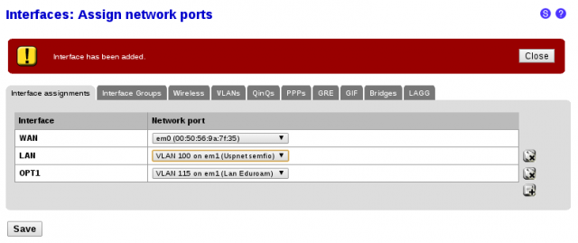
Com as VLANs configuradas, bastará adicionar uma nova interface e associar cada uma delas a uma das VLANs.

pfsense_criar_opt1

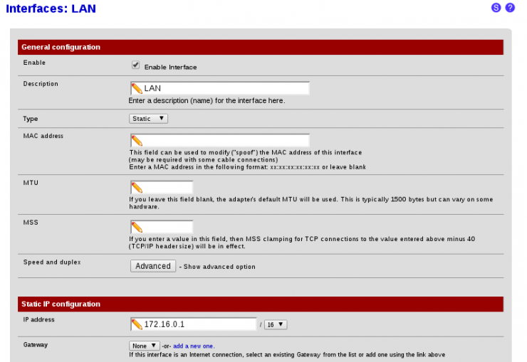
Abaixo esta um exemplo de configuração da interface LAN (USPnet semfio)

pfsense_lan

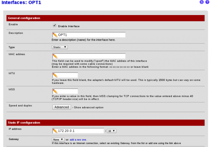
De modo semelhante à interface LAN, também configuraremos a interface OPT1 com um endereço IP.

pfsense_opt1

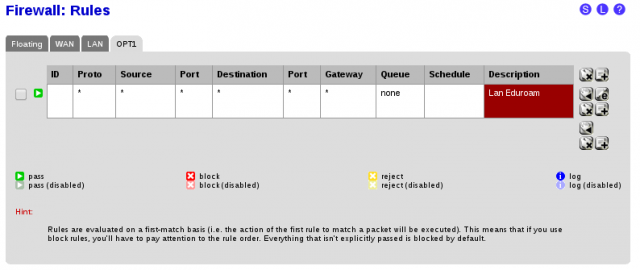
Devemos criar uma regra de firewall para liberar o tráafego na interface OPT1 (LAN eduroam).

pfsense_fw_opt1

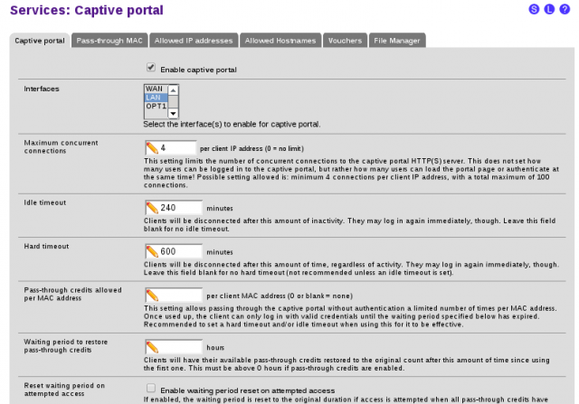
O serviço Captive Portal deverá estar ativo na interface LAN para autenticação dos usuário USPnet semfio.

captura_de_tela-8

O servidor DHCP deve estar habilitado a entregar IP aos clientes da LAN eduroam. Utilizamos o range 172.20.0.10 – 172.20.0.254

pfsense_dhcp_opt1


porplague70

How To Create And Configure VLANs In pfSense

How To Create And Configure VLANs In pfSense

pfSense is a customized version of FreeBSD tailored specifically for use as a perimeter firewall and router, managed entirely from a web browser or command line interface. pfSense includes a long list of other features, as well as a package system allowing its capabilities to be expanded even further. pfSense is free, open source software distributed under the BSD license.

A VLAN (“Virtual Local Area Network”) is a logical grouping of network hosts (and other resources) connected to administratively defined ports on a switch. This enables hosts to communicate as if the attached to the same physical medium, when in fact they may actually be located on different LAN segments. A VLAN is treated like its own subnet or broadcast domain, which means that Ethernet frames broadcast onto the network are only switched between the ports logically grouped within the same VLAN.

In this post I will describe how to create and configure VLANs in pfSense. Once configured, you’ll be able to route (or prevent routing) traffic between each VLAN, and each VLAN will be able to share the same Internet connection. To help explain the steps involved, we’ll create two static VLANs on a 24-port switch and trunk those VLANs from the switch to the LAN interface on pfSense, where we will assign each VLAN a unique /24 private IP subnet.

All steps involved assume that: 1) pfSense is installed correctly and providing basic Internet connectivity to an existing LAN interface; 2) the NIC (“Network Interface Controller”) assigned to the LAN interface supports IEEE 802.1Q VLAN tagging; and, 3) the switch connected to the LAN interface is capable of supporting the creation, configuration and trunking of port-based VLANs.

The software versions used in this post were as follows:

  • pfSense v2.1.2 (x32)

The switch used in this post was a Cisco model SG200-26; a so-called “smart switch,” featuring, among other things, Gigabit Ethernet, a web-based management interface, and simultaneous support for up to 256 port-based and IEEE 802.1Q tag-based VLANs.

Each switch, and its associated management interface, however, is different; therefore, you’ll need to make the appropriate adjustments when following the instructions in this post in order to successfully configure your particular switch.

Let’s get started…

Configuring The Switch

As you may recall, static VLANs, often referred to as “port-based” VLANs, are created by assigning switch ports to a preconfigured VLAN identifier. In our example, we’ll configure two static VLANs on our switch and assign them VLAN ID 10 and VLAN ID 20. Note that you can use any positive integer between 2 and 4094 you’d like for your VLAN ID, however, VLAN IDs 1 and 4095 should be avoided because, as a general rule, most switches by default assign all ports to VLAN ID 1, the “administrative” VLAN ID, and VLAN ID 4095 as the “discard” VLAN.

Begin by navigating to VLAN Management->Create VLAN and select “Add.” Enter a value of 10 in the “VLAN ID” field and enter a name to denote this particular VLAN in the “VLAN Name” field. In this example, we’ve used the name “vlan10.” When complete, select “Apply”. (See Figure 1)
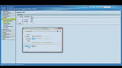
Screenshot showing the creation of a new VLAN ID 10 in the Cisco SG200-26 switch

Figure 1

Perform the same steps to create the second VLAN, this time assigning a value of 20 to the “VLAN ID” field and “vlan20” to the “VLAN Name” field. When complete, select “Apply” and you should see the newly minted VLANs listed (See Figure 2).
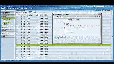
Screenshot showing that two VLANs have been created in the Cisco SG200-26 switch

Figure 2

Before assigning membership of a particular port to one of our new VLANs, we must first configure that port to be either an “Access” port or a “Trunk” port. Access ports are ports that are members of only one VLAN. This type of port is normally used for attaching end devices which are generally unaware of a VLAN membership, either because their NIC is incapable of tagging Ethernet frames a VLAN ID, or they are not configured to do so. Switch ports configured as Access ports remove any VLAN information from the Ethernet frame before it is sent to the device. Trunk ports on the other hand can carry multiple VLAN traffic, and are normally used to connect switches to other switches or to routers. It is very often the case that small-business grade switches, such as the Cisco SG200, designate each port as a Trunk port by default.

To keep our example simple, we’ll assume that the device(s) connected to the switch are not configured, or are unable to be configured, to tag Ethernet frames with a VLAN ID. Consequently, we’ll configure ports 1 and 2 as Access ports, and assign each membership in one of the two newly created VLANs. Furthermore, we’ll also assume that port 25 is currently being used to connect the switch to the pfSense LAN interface, and configure it as a Trunk port, assigning it membership in both of the newly created VLANs.

Navigate to VLAN Management->Interference Settings, select port 1 and then select “Edit”. Change the Interface VLAN Mode from Trunk to Access, then select “Apply” (See Figure 3). Now follow similar steps to configure port 2 as an Access port.
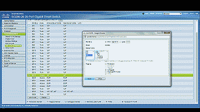
Screenshot showing port 1 being configured as an Access port in the Cisco SG200-26 switch

Figure 3

Next, navigate to VLAN Management->Port VLAN Membership, select port 1 and then select “Join VLAN”. Since Access ports can be added as untagged to only a single VLAN, we’ll need to first remove the default VLAN the switch automatically assigns to each port (usually VLAN 1). Highlight VLAN 1 by left-clicking on it, then select the arrow icon to remove it from the interface. Now highlight VLAN 10 by left-clicking on it, then select the arrow icon to add it to the interface, ensuring that “Untagged” is selected from among the options under “Tagging”. Select “Apply” when completed (See Figure 4). Now follow similar steps to join port 2 to VLAN 20.
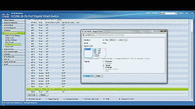
Screenshot showing port 1 being joined to VLAN 10 in the Cisco SG200-26 switch

Figure 4

With switch ports 1 and 2 configured as Access ports and joined to VLANs 10 and 20 respectively, any Ethernet frames that enter those ports will be tagged with the appropriate VLAN ID. Now let’s configure the port 25, the port that is connected to the LAN NIC in pfSense. This port will be configured as a Trunk port and joined to both VLAN 10 and 20 so that, in addition to passing the Ethernet frames from from devices attached to the other ports on the switch to pfSense, it will also pass Ethernet frames tagged with VLAN IDs 10 and 20 (from ports 1 and 2).

Ensure that port 25 is configure as a Trunk port, then navigate to VLAN Management->Port VLAN Membership, select port 25 and then select “Join VLAN”. Highlight VLAN 10 by left-clicking on it, then select the arrow icon to add it to the interface, ensuring that “Tagged” is selected from among the options under “Tagging”. Follow similar steps to join port 25 to VLAN 20, then select “Apply” when completed (See Figure 5).
Screenshot showing port 25 being joined to VLAN 10 and VLAN 20 in the Cisco SG200-26 switch

Figure 5

That’s it for configuring the switch. If your switch supports both a running configuration and a startup configuration, make sure to save the changes you’ve made to the startup configuration so that they are not lost should the switch reboot for any reason.

Configuring pfSense

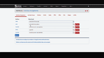
Now we need to create and configure VLANs 10 and 20 in pfSense. Navigate to Interfaces->assignand make note of the device driver name assigned to the LAN NIC. For our example we’ll assume the device name is “em2” (See Figure 6). The LAN interface will serve as the “parent interface” for the VLAN interfaces we will create in the next step.
Screenshot showing the device driver name assigned to the LAN NIC in pfSense

Figure 6

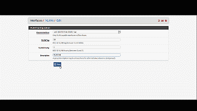
Next, navigate to Interfaces->assign->VLANs and select the “+” icon. In the subsequent screen, select “em2”, the LAN NIC interface, from among the options in the drop down list under “Parent interface”, and enter the value of 10 under “VLAN tag”. Add an optional description for this VLAN under “Description”, then select “Save” (See Figure 7). Follow similar steps to create the VLAN 20 interface.
Screenshot showing the creation of a VLAN interface in pfSense

Figure 7

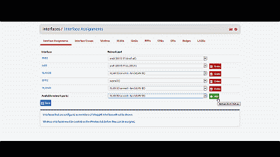
After creating the VLAN interfaces, return to Interfaces->assign and select the “+” icon to add an interface. Select “VLAN 10 on em2 (vlan10)” from among the options in the drop down list, then select “Save” (See Figure 8). Follow similar steps to add the VLAN 20 interface. At this point you’ll notice that under the “Interface” column pfSense has denoted VLAN 10 and VLAN 20 as “OPT1″ and OPT2” respectively. Don’t worry, we’ll address that next.
Screenshot showing the creation of a VLAN interface in pfSense

Figure 8

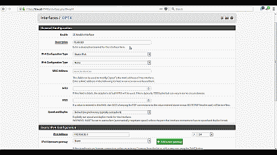
Navigate to Interfaces->OPT1 and select “Enable Interface”. Under “Description” replace “OPT1” with “VLAN 10”, then select “Static” from among the options in the drop down list under “Type”. For our example, we’ll use network 192.168.10.0/24 for VLAN 10 by assigning the static IP address 192.168.10.1 on this interface, and selecting the network mask of “24” from among the options in the drop list under the “Static IP configuration” section. The other parameters can remain at their default values. Select “Save” and “Apply changes” when complete (See Figure 9). Follow similar steps to enable the OPT2 interface, assigning it the name “VLAN 20” with a static IP address of 192.168.20.1 and a network mask of 24. Now if you navigating back to Interfaces->assign you will see VLAN 10 and VLAN 20 listed and labeled with the description you added when enabling the interface in the previous steps.
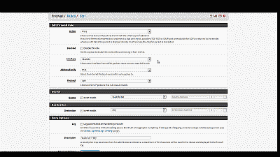
Screenshot showing the VLAN 10 interface being enabled and configured in pfSense

Figure 9

Next, we need to build a firewall rule for our two new VLANs so that traffic can pass to / from the WAN interface, and by extension, to the Internet. Navigate to Firewall->Rules and select the tab for VLAN 10. Select the “+” icon to create a new rule. For our example, we’ll build a simple outbound pass rule for any protocol in VLAN 10, similar to the way a typical LAN outbound pass rule would be configured. Select “any” from among the options in the drop down list Under “Protocol”, and under “Source” select “VLAN 10 subnet” from among the options in the drop list under the “Type” field. If desired, you may enter a description of this newly created rule for your reference under “Description”. The other parameters can remain at their default values. Select “Save” and “Apply changes” when complete (See Figure 10). Now select the tab for VLAN 20 and follow similar steps to create its firewall rule.
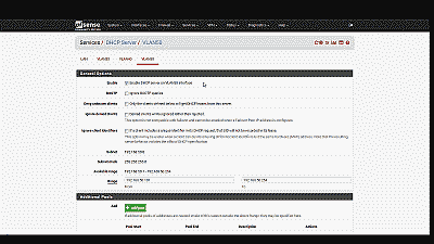
Screenshot showing the creation of a firewall rule for VLAN 10 in pfSense

Figure 10

Unless you plan to assign static IP addresses to host devices, you’ll want to configure a DHCP server for each of the new VLANs. Navigate to Services->DHCP server and select the tab for VLAN10. Select “Enable DHCP server on VLAN10 interface”, then enter the range of IP addresses within the network 192.168.10.0/24 you’d like the DHCP server to use under “Range”. Finally, enter an IP address for the network gateway under “Gateway”. Unless your requirements call for something different, you would typically use the IP address assigned to this interface as the gateway address. For our example this address will be 192.168.10.1. The other parameters can remain at their default values. Select “Save” when complete (See Figure 11). Follow similar steps to configure the DHCP server for VLAN 20, this time entering a range of IP addresses within the network 192.168.10.0/24, and 192.168.20.1 as the IP address for the network gateway.
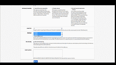
Screenshot showing the creation and configuration of a DHCP server for VLAN 10 in pfSense

Figure 11

Wrapping up

At this point the LAN switch and pfSense should be configured to support VLAN 10 and VLAN 20. To test, connect a host device such as a desktop or laptop computer to port 1 on the switch. If you’ve configured everything as described, you should receive an IP address within the DHCP address range you’ve specified for VLAN 10 network 192.168.10.0/24. The default gateway, DHCP server and DNS server addresses should be 192.168.10.1. You should also have Internet connectivity. Connecting this same device to port 2 of the switch should yield the same status: you should receive an IP address within the DHCP address range you’ve specified for VLAN 20 network 192.168.20.0/24; the default gateway, DHCP server and DNS server addresses should all have address 192.168.20.1; and once again you should have Internet access.

Be aware that as currently configured, each VLAN is routed to all other VLANs. If you would like to disallow some or all traffic to/from a particular VLAN you must create firewall rules explicitly stating what traffic should not be routed. Keep in mind that pfSense evaluates firewall rules on a first-match basis (i.e. the action of the first rule to match a packet will be executed). So, for example, if you wanted to block all VLAN 10 traffic from reaching VLAN 20 you might create a rule to that effect and move it before the one we created previously to route all VLAN 10 traffic to any destination (See Figure 12).
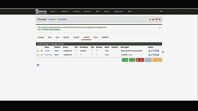
Screenshot showing the placement of a firewall rule blocking all VLAN 10 to VLAN 20 traffic in pfSense

Figure 12

Conclusion

VLAN support in pfSense is not hard to configure nor complicated to manage, assuming your switch and NICs support this capability. To help explain the steps involved, we created two static VLANs on a commodity 24-port small-business switch and trunked those VLANs to the LAN interface on pfSense. We then created and added the VLAN interfaces, created the requisite firewall rules, and assigned each VLAN a unique /24 private IP subnet with host addressing handled using DHCP. Each VLAN is able to share the pfSense’s Internet connection and we are able further configure pfSense to prevent routing traffic between each VLAN, if desired.

porplague70

How to install pfsense in Virtualbox

How to install pfsense in Virtualbox

How-to-install-pfsense-in-VirtualboxHow to install pfsense in Virtualbox :-

pfSense is a free, open source customized distribution of FreeBSD tailored for use as a firewall and router. In addition to being a powerful, flexible firewalling and routing platform, it includes a long list of related features and a package system allowing further expandability without adding bloat and potential security vulnerabilities to the base distribution.
With Pfsense you can easily install and manage Squid proxy server , Squid Guard , Secure WiFi Hotspotand many other services. For me it,s really working amazing. i will try to wrtie more and more on pfsense technologies.

Today i am going to show you How to install pfsense in virtualbox ?

For this You need a .iso image file from pfsense. Go to the http://www.pfsense.org and click on thedownload section and select any mirror server that one is close to your location. and download the file with .img.gz extensions and also download the .md5 and .sha file.

How-to-install-pfsense-in-Virtualbox1

Now open your Virtual box and click on the New to create a new machine. select the Type BSD and version FreeBSD. if your system is 64-bit, then select version FreeBSD (64-bit)

How-to-install-pfsense-in-Virtualbox1

and select your RAM 512 MB minimum and provide the location of virtual hard disk location on your PC and select the hard drive file type VDI.

Now select the Setting option. Click on the network and in the Adapter 1 select the option Attached toBridge Adapter.

How-to-install-pfsense-in-Virtualbox1

Now click on the Adapter 2 , select the option Enable network Adapter and select the option Internal network.

How-to-install-pfsense-in-Virtualbox1

Now click on the Storage option > from the cd menu select a choose a virtual CD/DVD option and location your pfsense image file on your hard-disk.

How-to-install-pfsense-in-Virtualbox1

Now click on start to power on your virtual box machine. now select the option 1 ( Boot pfsense (default).

How-to-install-pfsense-in-Virtualbox1

Now it will you create Vlan , select No and now enter the em0 as WAN interface name.

How-to-install-pfsense-in-Virtualbox1

Now select the option < Accept these settings >

How-to-install-pfsense-in-Virtualbox1

Now select the option < Quick /Easy install > .and click on ok.

How-to-install-pfsense-in-Virtualbox1

now it will start installation

How-to-install-pfsense-in-Virtualbox1

Now select the Standard kernel option.

How-to-install-pfsense-in-Virtualbox1

Now it will ask to reboot , Remove the Image file from the Device menu and reboot it.

How-to-install-pfsense-in-Virtualbox1

now you are able to connect to pfsense.

How-to-install-pfsense-in-Virtualbox1