A VLAN (“Virtual Local Area Network”) is a logical grouping of network hosts (and other resources) connected to administratively defined ports on a switch. This enables hosts to communicate as if the attached to the same physical medium, when in fact they may actually be located on different LAN segments. A VLAN is treated like its own subnet or broadcast domain, which means that Ethernet frames broadcast onto the network are only switched between the ports logically grouped within the same VLAN.
In this post I will describe how to create and configure VLANs in pfSense. Once configured, you’ll be able to route (or prevent routing) traffic between each VLAN, and each VLAN will be able to share the same Internet connection. To help explain the steps involved, we’ll create two static VLANs on a 24-port switch and trunk those VLANs from the switch to the LAN interface on pfSense, where we will assign each VLAN a unique /24 private IP subnet.
All steps involved assume that: 1) pfSense is installed correctly and providing basic Internet connectivity to an existing LAN interface; 2) the NIC (“Network Interface Controller”) assigned to the LAN interface supports IEEE 802.1Q VLAN tagging; and, 3) the switch connected to the LAN interface is capable of supporting the creation, configuration and trunking of port-based VLANs.
The software versions used in this post were as follows:
The switch used in this post was a Cisco model SG200-26; a so-called “smart switch,” featuring, among other things, Gigabit Ethernet, a web-based management interface, and simultaneous support for up to 256 port-based and IEEE 802.1Q tag-based VLANs.
Each switch, and its associated management interface, however, is different; therefore, you’ll need to make the appropriate adjustments when following the instructions in this post in order to successfully configure your particular switch.
Let’s get started…
Configuring The Switch
As you may recall, static VLANs, often referred to as “port-based” VLANs, are created by assigning switch ports to a preconfigured VLAN identifier. In our example, we’ll configure two static VLANs on our switch and assign them VLAN ID 10 and VLAN ID 20. Note that you can use any positive integer between 2 and 4094 you’d like for your VLAN ID, however, VLAN IDs 1 and 4095 should be avoided because, as a general rule, most switches by default assign all ports to VLAN ID 1, the “administrative” VLAN ID, and VLAN ID 4095 as the “discard” VLAN.
Begin by navigating to VLAN Management->Create VLAN and select “Add.” Enter a value of 10 in the “VLAN ID” field and enter a name to denote this particular VLAN in the “VLAN Name” field. In this example, we’ve used the name “vlan10.” When complete, select “Apply”. (See Figure 1)
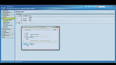
Figure 1
Perform the same steps to create the second VLAN, this time assigning a value of 20 to the “VLAN ID” field and “vlan20” to the “VLAN Name” field. When complete, select “Apply” and you should see the newly minted VLANs listed (See Figure 2).
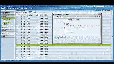
Figure 2
Before assigning membership of a particular port to one of our new VLANs, we must first configure that port to be either an “Access” port or a “Trunk” port. Access ports are ports that are members of only one VLAN. This type of port is normally used for attaching end devices which are generally unaware of a VLAN membership, either because their NIC is incapable of tagging Ethernet frames a VLAN ID, or they are not configured to do so. Switch ports configured as Access ports remove any VLAN information from the Ethernet frame before it is sent to the device. Trunk ports on the other hand can carry multiple VLAN traffic, and are normally used to connect switches to other switches or to routers. It is very often the case that small-business grade switches, such as the Cisco SG200, designate each port as a Trunk port by default.
To keep our example simple, we’ll assume that the device(s) connected to the switch are not configured, or are unable to be configured, to tag Ethernet frames with a VLAN ID. Consequently, we’ll configure ports 1 and 2 as Access ports, and assign each membership in one of the two newly created VLANs. Furthermore, we’ll also assume that port 25 is currently being used to connect the switch to the pfSense LAN interface, and configure it as a Trunk port, assigning it membership in both of the newly created VLANs.
Navigate to VLAN Management->Interference Settings, select port 1 and then select “Edit”. Change the Interface VLAN Mode from Trunk to Access, then select “Apply” (See Figure 3). Now follow similar steps to configure port 2 as an Access port.
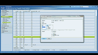
Figure 3
Next, navigate to VLAN Management->Port VLAN Membership, select port 1 and then select “Join VLAN”. Since Access ports can be added as untagged to only a single VLAN, we’ll need to first remove the default VLAN the switch automatically assigns to each port (usually VLAN 1). Highlight VLAN 1 by left-clicking on it, then select the arrow icon to remove it from the interface. Now highlight VLAN 10 by left-clicking on it, then select the arrow icon to add it to the interface, ensuring that “Untagged” is selected from among the options under “Tagging”. Select “Apply” when completed (See Figure 4). Now follow similar steps to join port 2 to VLAN 20.
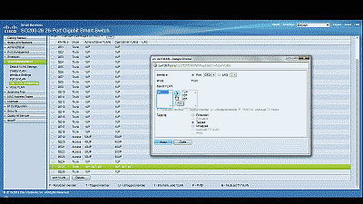
Figure 4
With switch ports 1 and 2 configured as Access ports and joined to VLANs 10 and 20 respectively, any Ethernet frames that enter those ports will be tagged with the appropriate VLAN ID. Now let’s configure the port 25, the port that is connected to the LAN NIC in pfSense. This port will be configured as a Trunk port and joined to both VLAN 10 and 20 so that, in addition to passing the Ethernet frames from from devices attached to the other ports on the switch to pfSense, it will also pass Ethernet frames tagged with VLAN IDs 10 and 20 (from ports 1 and 2).
Ensure that port 25 is configure as a Trunk port, then navigate to VLAN Management->Port VLAN Membership, select port 25 and then select “Join VLAN”. Highlight VLAN 10 by left-clicking on it, then select the arrow icon to add it to the interface, ensuring that “Tagged” is selected from among the options under “Tagging”. Follow similar steps to join port 25 to VLAN 20, then select “Apply” when completed (See Figure 5).
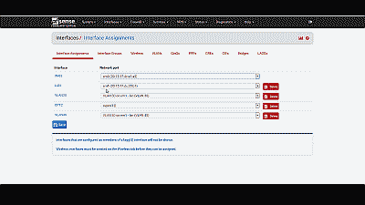
Figure 5
That’s it for configuring the switch. If your switch supports both a running configuration and a startup configuration, make sure to save the changes you’ve made to the startup configuration so that they are not lost should the switch reboot for any reason.
Configuring pfSense
Now we need to create and configure VLANs 10 and 20 in pfSense. Navigate to Interfaces->assignand make note of the device driver name assigned to the LAN NIC. For our example we’ll assume the device name is “em2” (See Figure 6). The LAN interface will serve as the “parent interface” for the VLAN interfaces we will create in the next step.
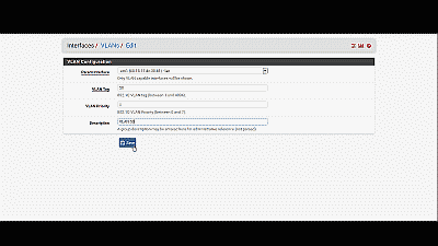
Figure 6
Next, navigate to Interfaces->assign->VLANs and select the “+” icon. In the subsequent screen, select “em2”, the LAN NIC interface, from among the options in the drop down list under “Parent interface”, and enter the value of 10 under “VLAN tag”. Add an optional description for this VLAN under “Description”, then select “Save” (See Figure 7). Follow similar steps to create the VLAN 20 interface.
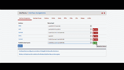
Figure 7
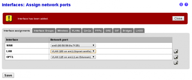
After creating the VLAN interfaces, return to Interfaces->assign and select the “+” icon to add an interface. Select “VLAN 10 on em2 (vlan10)” from among the options in the drop down list, then select “Save” (See Figure 8). Follow similar steps to add the VLAN 20 interface. At this point you’ll notice that under the “Interface” column pfSense has denoted VLAN 10 and VLAN 20 as “OPT1″ and OPT2” respectively. Don’t worry, we’ll address that next.
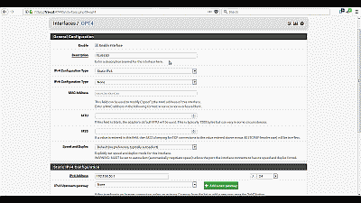
Figure 8
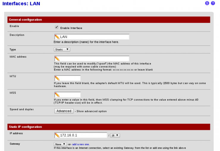
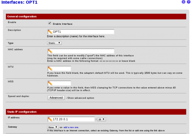
Navigate to Interfaces->OPT1 and select “Enable Interface”. Under “Description” replace “OPT1” with “VLAN 10”, then select “Static” from among the options in the drop down list under “Type”. For our example, we’ll use network 192.168.10.0/24 for VLAN 10 by assigning the static IP address 192.168.10.1 on this interface, and selecting the network mask of “24” from among the options in the drop list under the “Static IP configuration” section. The other parameters can remain at their default values. Select “Save” and “Apply changes” when complete (See Figure 9). Follow similar steps to enable the OPT2 interface, assigning it the name “VLAN 20” with a static IP address of 192.168.20.1 and a network mask of 24. Now if you navigating back to Interfaces->assign you will see VLAN 10 and VLAN 20 listed and labeled with the description you added when enabling the interface in the previous steps.
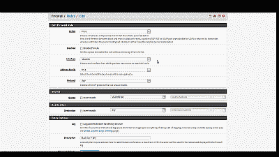
Figure 9
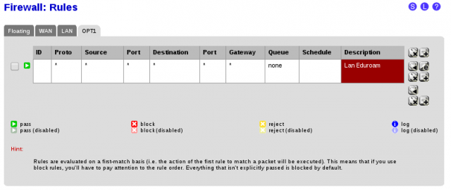
Next, we need to build a firewall rule for our two new VLANs so that traffic can pass to / from the WAN interface, and by extension, to the Internet. Navigate to Firewall->Rules and select the tab for VLAN 10. Select the “+” icon to create a new rule. For our example, we’ll build a simple outbound pass rule for any protocol in VLAN 10, similar to the way a typical LAN outbound pass rule would be configured. Select “any” from among the options in the drop down list Under “Protocol”, and under “Source” select “VLAN 10 subnet” from among the options in the drop list under the “Type” field. If desired, you may enter a description of this newly created rule for your reference under “Description”. The other parameters can remain at their default values. Select “Save” and “Apply changes” when complete (See Figure 10). Now select the tab for VLAN 20 and follow similar steps to create its firewall rule.
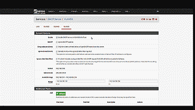
Figure 10
Unless you plan to assign static IP addresses to host devices, you’ll want to configure a DHCP server for each of the new VLANs. Navigate to Services->DHCP server and select the tab for VLAN10. Select “Enable DHCP server on VLAN10 interface”, then enter the range of IP addresses within the network 192.168.10.0/24 you’d like the DHCP server to use under “Range”. Finally, enter an IP address for the network gateway under “Gateway”. Unless your requirements call for something different, you would typically use the IP address assigned to this interface as the gateway address. For our example this address will be 192.168.10.1. The other parameters can remain at their default values. Select “Save” when complete (See Figure 11). Follow similar steps to configure the DHCP server for VLAN 20, this time entering a range of IP addresses within the network 192.168.10.0/24, and 192.168.20.1 as the IP address for the network gateway.
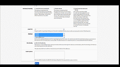
Figure 11
Wrapping up
At this point the LAN switch and pfSense should be configured to support VLAN 10 and VLAN 20. To test, connect a host device such as a desktop or laptop computer to port 1 on the switch. If you’ve configured everything as described, you should receive an IP address within the DHCP address range you’ve specified for VLAN 10 network 192.168.10.0/24. The default gateway, DHCP server and DNS server addresses should be 192.168.10.1. You should also have Internet connectivity. Connecting this same device to port 2 of the switch should yield the same status: you should receive an IP address within the DHCP address range you’ve specified for VLAN 20 network 192.168.20.0/24; the default gateway, DHCP server and DNS server addresses should all have address 192.168.20.1; and once again you should have Internet access.
Be aware that as currently configured, each VLAN is routed to all other VLANs. If you would like to disallow some or all traffic to/from a particular VLAN you must create firewall rules explicitly stating what traffic should not be routed. Keep in mind that pfSense evaluates firewall rules on a first-match basis (i.e. the action of the first rule to match a packet will be executed). So, for example, if you wanted to block all VLAN 10 traffic from reaching VLAN 20 you might create a rule to that effect and move it before the one we created previously to route all VLAN 10 traffic to any destination (See Figure 12).
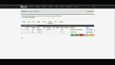
Figure 12
Conclusion
VLAN support in pfSense is not hard to configure nor complicated to manage, assuming your switch and NICs support this capability. To help explain the steps involved, we created two static VLANs on a commodity 24-port small-business switch and trunked those VLANs to the LAN interface on pfSense. We then created and added the VLAN interfaces, created the requisite firewall rules, and assigned each VLAN a unique /24 private IP subnet with host addressing handled using DHCP. Each VLAN is able to share the pfSense’s Internet connection and we are able further configure pfSense to prevent routing traffic between each VLAN, if desired.


